
-
Please try to be as accurate as possible with your search.
-
We can quote you on 1000s of specialist parts, even if they are not listed on our website.
-
We can't find any results for “”.
Industrial Controllers and EN 61000 EMC Compliance: A Veteran Integrator’s Field Guide
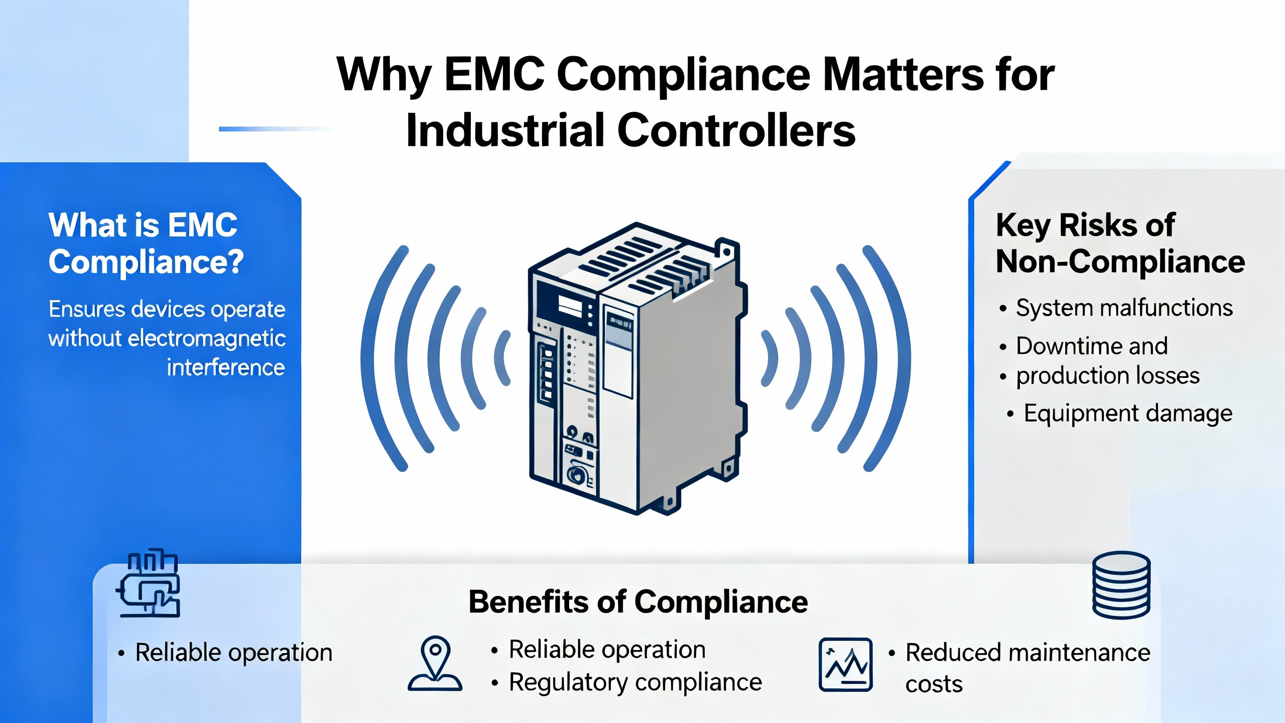
Why EMC Compliance Matters for Industrial Controllers
In a factory or process plant, industrial controllers sit at the center of everything that moves, heats, mixes, cuts, or measures. They read low‑level sensor signals, drive actuators, talk to drives and power supplies, and coordinate entire lines. When electromagnetic interference sneaks in, these controllers are often the first place you notice trouble: nuisance trips, frozen HMIs, drives that stop for no obvious reason, or analog readings that quietly drift just enough to ruin a batch.
Electromagnetic compatibility, or EMC, is simply the ability of a device to operate correctly in its electromagnetic environment without creating intolerable interference for other equipment. Industry introductions from measurement providers such as Keysight and EMC labs such as UL Solutions all converge on the same definition: you must both keep your own emissions under control and be robust against what the environment throws at you.
Industrial electronics are particularly vulnerable. As Cadence explains in its guidance on EMC for industrial systems, industrial electronics cover everything from power switches and drives to sensors, controllers, and RF circuits. Many of those devices operate at millivolt or milliwatt levels. Analog sensors that measure temperature, pressure, flow, position, voltage, or current are a good example. They drive decisions like “start,” “continue,” or “stop” in automation systems. When electromagnetic interference corrupts these signals, the controller can make the wrong decision, leading to erratic behavior or even temporary shutdowns that carry a very real financial impact.
On top of that, modern industrial sites are electrically harsh. Heavy motors, variable‑speed drives, welding systems, switching power supplies, and high‑current conductors create strong magnetic fields, fast transients, surges, and broad‑band RF noise. Siretta’s discussion of industrial routers and EN 61000-6-2 paints the same picture: industrial environments are filled with radiated and conducted interference, electrostatic discharge, and power quality variations. If your controller cannot ride through that, your uptime will suffer.
This is why EMC standards such as the EN 61000 series matter so much. They give system integrators and manufacturers a common, testable definition of “robust enough” for a given environment. For industrial controllers, EN 61000 compliance is no longer a nice‑to‑have marketing label; it is part of the basic fitness for purpose.
How the EN 61000 Framework Is Organized
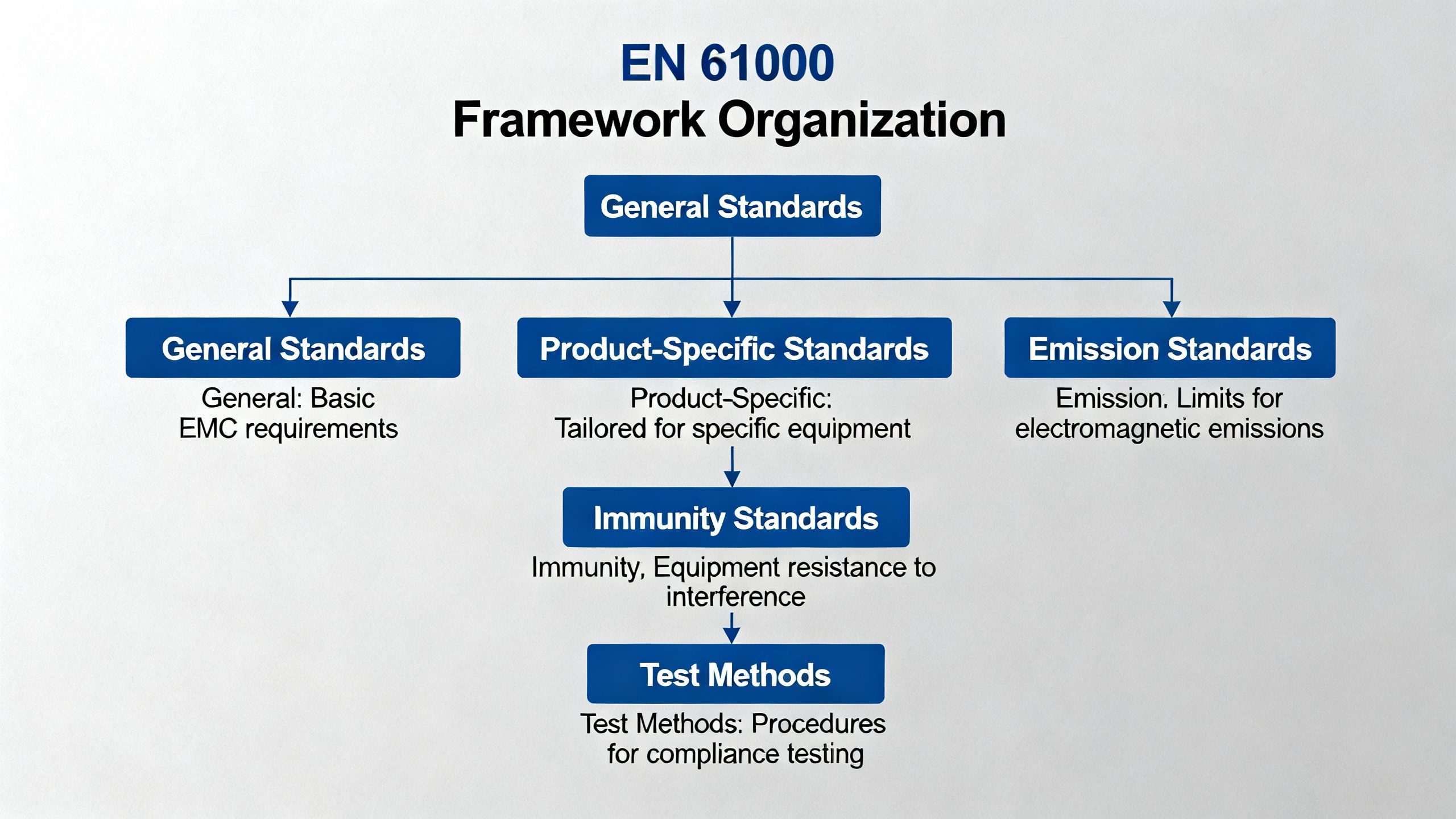
The EN 61000 standards are the European adoption of the IEC 61000 series. UL Solutions and Ametek CTS both describe IEC 61000 as a foundational global EMC framework: it defines how to measure emissions and immunity, what levels you must meet in different environments, and how to classify products.
Advanced Energy and Ametek outline the structure in three layers. Basic standards, primarily EN 61000-4-x, define the test and measurement techniques and the test levels for specific disturbance phenomena such as electrostatic discharge, radiated RF, surges, and voltage dips. Generic standards, mainly EN 61000-6-x, define overall emission and immunity requirements for broad environments like residential/light industrial or industrial. Product and product‑family standards then refine those requirements for specific categories such as medical equipment or measurement and control devices.
For any industrial controller aimed at the European market, the EN 61000 framework usually plays two roles at once. It gives you technical targets for design and test, and, under the EU EMC Directive described by ComplianceGate, it provides a path to presumption of conformity. When you apply the relevant harmonized EN 61000 standards, you can show that your controller meets the essential EMC requirements required for CE marking and legal market access.
Generic Standards for Industrial Environments: EN 61000‑6‑x
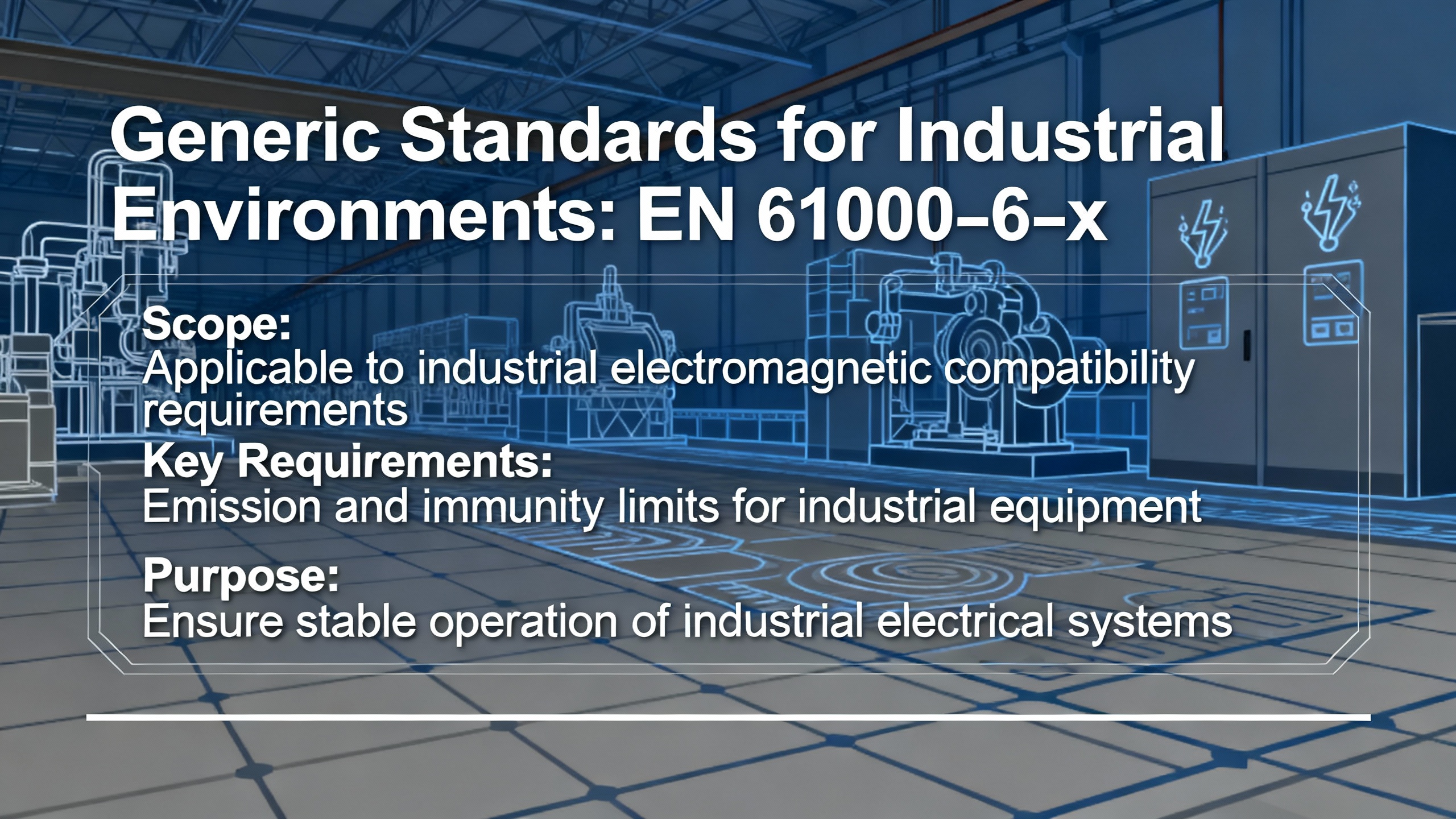
Industrial controllers rarely live in residential environments; they live in cabinets on noisy factory floors. That is where the generic standards EN 61000‑6‑2 and EN 61000‑6‑4 come in.
Cadence and UL Solutions both describe EN 61000‑6‑2 as the generic EMC immunity standard for equipment used in industrial locations. It specifies immunity requirements up to very high frequencies for conducted and radiated RF disturbances, electrostatic discharge, electrical fast transients, surges, conducted RF on cables, and power‑frequency magnetic fields. Siretta emphasizes that EN 61000‑6‑2 is targeted at harsh industrial conditions with strong interferers such as motors, power supplies, and switching transients. For a controller, compliance with EN 61000‑6‑2 means you have demonstrated that it continues to operate correctly under those disturbances, or at least fails in a controlled, recoverable way defined by the standard.
On the emission side, EN 61000‑6‑4 sets generic limits for electrical and electronic equipment in industrial environments. Cadence notes that EN 61000‑6‑4 covers emissions from about 9 kHz up to hundreds of gigahertz for equipment intended for indoor and outdoor industrial sites and applies where EN 61000‑6‑3 (for residential and light industrial) does not. UL Solutions confirms that EN 61000‑6‑4 is the industrial counterpart of EN 61000‑6‑3, with limits appropriate for Class A industrial equipment.
For completeness, EN 61000‑6‑1 and EN 61000‑6‑3 cover immunity and emissions for residential, commercial, and light‑industrial environments. Celectronics explains that these standards are intended for products sold to the general public and used in homes and offices, generally with tighter emission limits but less severe immunity levels than heavy industrial standards. That matters if your controller is used in small building automation systems or light‑industrial labs rather than on a heavy production line.
The generic standards, especially EN 61000‑6‑2 and EN 61000‑6‑4, are the backbone of EMC claims for industrial controllers in Europe. They tell test labs which basic tests to perform and at what levels. They also help integrators quickly check whether a controller is meant for industrial panels or only for lighter environments.
Basic Test Standards That Hit Industrial Controllers
Behind the generic EN 61000‑6‑x labels, the real work is done by the EN 61000‑4‑x basic standards. Advanced Energy, UL Solutions, Intertek, and InfiniPower collectively outline the key tests that industrial controllers are likely to face.
Electrostatic discharge immunity is covered by EN 61000‑4‑2. Intertek notes that testing uses contact and air discharges, and Advanced Energy describes typical levels on the order of a few kilovolts for contact discharge and significantly higher for air discharge in more severe environments. For a controller, this test validates that front panels, I/O connectors, and housings will not cause lock‑ups when an operator touches them with a charged tool or when dry air and synthetic clothing turn the plant into a static generator.
Radiated RF immunity is defined in EN 61000‑4‑3. Advanced Energy notes that tests commonly sweep from about 80 MHz to 1 GHz or beyond, with field strengths often around 3 V/m for residential and commercial environments and up to roughly 10 V/m for industrial applications. This is where you learn whether your controller can survive in an environment filled with industrial wireless networks, high‑power radios, or broadband noise from large equipment.
Conducted RF immunity on cables is addressed by EN 61000‑4‑6, where RF currents are injected into power and signal lines over a band from roughly 150 kHz to 80 MHz at specified levels. For controllers with long fieldbus runs or I/O wiring, this test is a stress test for your filtering and PCB layout.
Fast transient or burst immunity, covered by EN 61000‑4‑4, simulates switching transients on power and signal lines. Advanced Energy highlights test levels from hundreds of volts to several kilovolts, depending on the environment. In practice, this is where poor filtering on digital I/O or relay outputs shows up as unexpected resets or spurious transitions.
Surge immunity, specified in EN 61000‑4‑5, represents high‑energy pulses from events such as lightning or power line faults. Advanced Energy notes that test levels can reach a few kilovolts line‑to‑line or line‑to‑earth. This test is critical for controllers directly connected to long runs or outdoor cables, and it often drives surge protection and isolation decisions in the design.
Power‑frequency magnetic field immunity is covered by EN 61000‑4‑8. Intertek notes that tests can reach tens of amperes per meter, simulating installation near transformers or high‑current busbars. For controllers installed in tight cabinets with large drives or contactors, this test validates that the PCB layout and shielding keep low‑level circuits stable.
Voltage dips, short interruptions, and voltage variations on AC inputs are handled by EN 61000‑4‑11. InfiniPower explains that this standard covers equipment up to 16 A per phase and defines test profiles such as short interruptions to zero volts for half a cycle to a cycle, moderate dips to 40–70 percent of nominal for tens of cycles, and longer shallow sags of about 80 percent for hundreds of cycles on 50 or 60 Hz systems. Tests must be run sequentially with multiple repetitions at each level. For controllers with integrated power supplies, this standard is not academic. It proves whether your control CPU and outputs ride through common grid disturbances, restart cleanly, and avoid unsafe behavior or data corruption.
Power quality and grid emissions are covered by standards in the EN 61000‑3 family. Pacific Power and UL Solutions list EN 61000‑3‑2 and EN 61000‑3‑12 for harmonic current emissions and EN 61000‑3‑3 and EN 61000‑3‑11 for flicker and voltage fluctuations on public low‑voltage systems. While these are often associated with larger loads, they can still be relevant when controllers incorporate higher‑power supplies or auxiliary loads; they define how much distortion and flicker the equipment is allowed to impose on the grid.
Together, these EN 61000‑4‑x and EN 61000‑3‑x standards define a very concrete question for a controller: under specific, repeatable disturbances, does it keep doing its job, or does it fail in a controlled and acceptable way?
The EN 61000 Performance Criteria and What They Mean in Practice
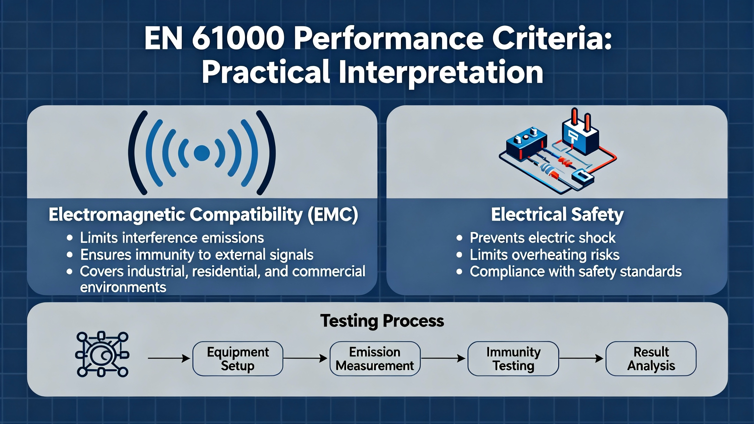
Keystone Compliance describes how IEC and EN 61000 immunity tests are judged using performance criteria. For industrial controllers, understanding these criteria is more than a paperwork exercise; it is how you translate test reports into operational expectations.
Performance criterion A means the equipment operates as intended during and after the test without unacceptable degradation or loss of function. In controller terms, that means logic execution, communications, and I/O all remain within specified tolerances while the interference is applied and after it is removed.
Performance criterion B allows temporary degradation during the test but demands that the equipment operate as intended afterward with no unacceptable degradation. For a controller, this might allow a minor, self‑recovering disturbance during a surge pulse, provided the system returns to normal operation once the disturbance is gone and no permanent change in state or data occurs beyond what is agreed in the test plan.
Performance criterion C allows a temporary loss of function during the test, provided the equipment recovers automatically or through normal use of controls, without special intervention. In a controller context, this might correspond to a controlled restart after a severe voltage dip, as long as the restart behavior is documented and acceptable for the application.
Before testing, Keystone notes that manufacturers must define the functional description and performance criteria in detail and provide any required external protection devices. For an industrial controller supplier, this means being explicit about which functions must remain rock‑solid (for example, safety‑related inputs), which can tolerate momentary disturbances, and how the device behaves during and after a disturbance. For integrators, it is important to read these definitions in the test report and confirm they align with how the controller will be used in the actual machine or process.
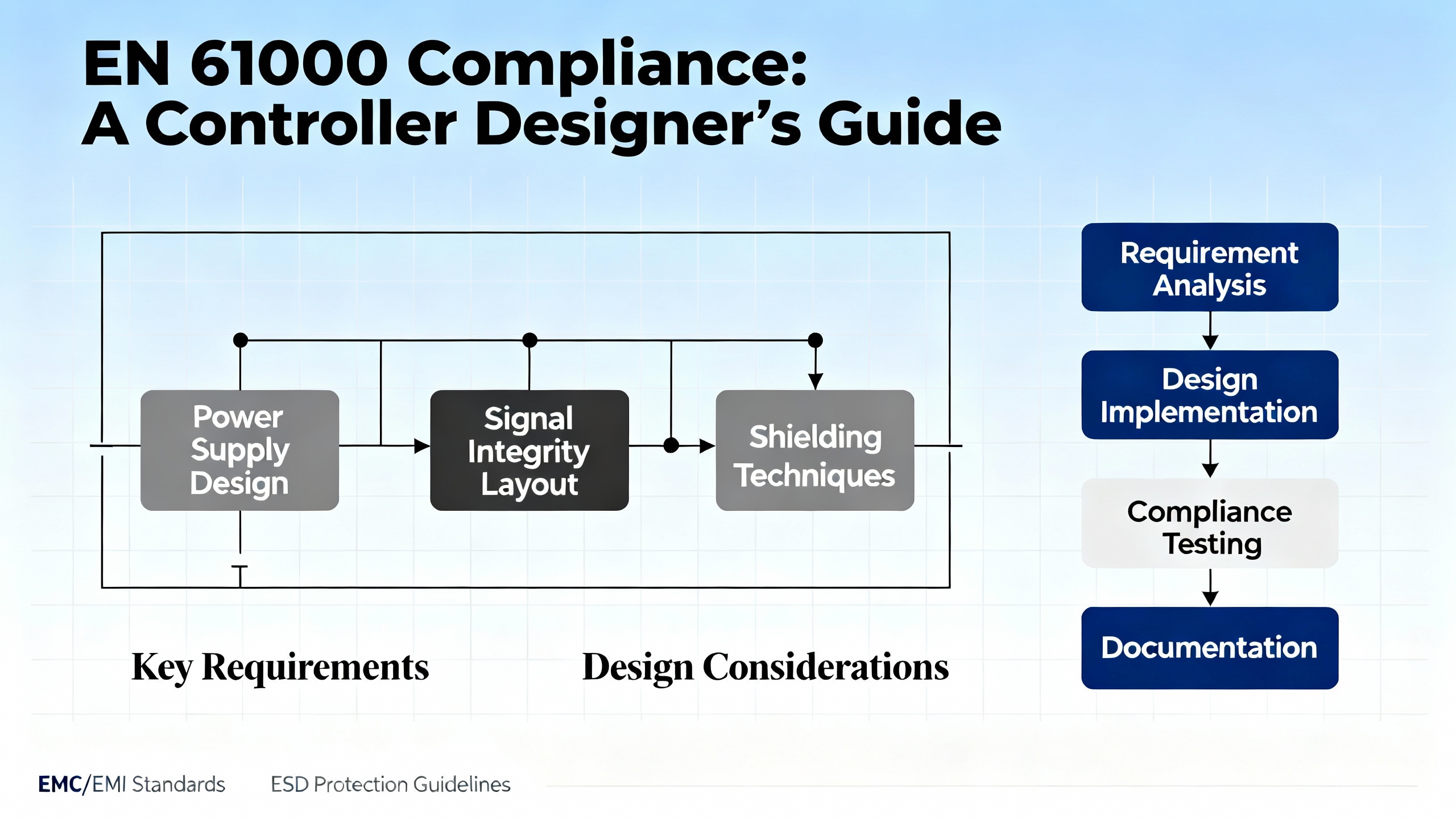
EN 61000 Compliance from a Controller Designer’s Perspective
Designing an industrial controller to meet EN 61000 is not about sprinkling ferrites on a finished board. Advanced Energy, Monolithic Power Systems, and Keysight all stress the same principle: EMC must be treated as a design requirement from the start.
On the PCB, good EMC practice for switch‑mode power supplies and digital logic includes minimizing loop areas in high‑current switching paths, using solid ground planes to control return currents, and separating noisy and sensitive circuits. Monolithic Power highlights the need to control differential‑mode and common‑mode noise through careful layout, filtering, and sometimes shielding. That is especially important in controllers with embedded power supplies or high‑speed interfaces.
Filtering is another pillar. Input filters close to power and signal connectors, common‑mode chokes on noisy lines, and decoupling networks placed at the right points help meet both conducted emission limits and immunity targets. Advanced Energy ties this directly to EN 61000‑4 tests: proper line filtering and surge protection are essential to pass fast transient and surge immunity without unwanted resets or damage.
Shielding and bonding also matter. Ametek CTS notes that IEC EMC standards include installation and mitigation guidance under the 61000‑5 series, while Keysight and Monolithic Power emphasize robust bonding and grounding schemes. For controllers, that translates into clear recommendations on cabinet bonding, shield termination for cables, and segregation of routing inside the enclosure.
Controlling rise and fall times and limiting high dV/dt and dI/dt edges in switching circuits are important to reduce emissions. That can mean choosing slower edge‑rate drivers where possible or adding snubbers and damping networks, as described in design guidance referenced by Advanced Energy and Monolithic Power.
Beyond the hardware, you must plan for testability. Keysight, Monolithic Power, and InfiniPower all recommend early pre‑compliance testing. That can involve small chambers or GTEM cells, line impedance stabilization networks for conducted emissions, and near‑field probes to sniff hotspots. On the immunity side, programmable AC and DC sources, such as the grid simulators and AC sources described by Pacific Power and InfiniPower, allow you to emulate EN 61000‑4‑11 dips and other disturbances in‑house before you ever book time at an accredited lab.
When EN 61000 is treated as a first‑order design constraint, controllers have a much better chance of passing formal testing the first time. That is not just about avoiding re‑test fees; it is about avoiding late layout spins and schedule slips that ripple through entire projects.
The System Integrator’s View: Controller Compliance Is Necessary but Not Sufficient
From a systems integration standpoint, a controller with EN 61000 certification is a good starting point, not the finish line. Intertek’s description of in‑situ EMC testing for large machinery underlines why. Even when individual devices comply with EN 61000 standards in the lab, the complete installation, with real wiring, grounding, and nearby equipment, can behave differently.
The EMC Directive explicitly calls out fixed installations and requires that they follow good engineering practice. ComplianceGate explains that manufacturers must provide user instructions that describe how to install and use the equipment so that EMC performance is not compromised. For controllers, that includes specifying shield terminations, grounding schemes, separation from power cables, and any required external protection devices or filters.
Keystone notes that EMC tests are performed on a port‑by‑port basis and that manufacturers are expected to provide representative system configurations and terminations. In the field, integrators often deviate from those exact setups. Longer cables, different cable types, and unplanned proximity to noisy equipment can all change EMC behavior.
As a result, even with a fully EN 61000‑compliant controller, you still need to treat EMC as a system‑level discipline. That includes cabinet layout, cable routing, bonding between panels and machine frames, and coordination of grounding across power, I/O, and communication networks. In demanding applications or very large installations, in‑situ testing like the services Intertek describes can be the only way to validate real‑world EMC performance.
Pros and Cons of Specifying EN 61000‑Compliant Industrial Controllers
Specifying industrial controllers that carry EN 61000 compliance has clear benefits but also some trade‑offs that project teams should understand.
On the positive side, EMC compliance directly improves reliability. Siretta notes that equipment designed to EN 61000‑6‑2 continues to function correctly under significant electromagnetic disturbances common in factories. That translates into fewer unexplained failures, fewer nuisance trips, and a higher level of confidence for safety‑critical applications. UL Solutions and ComplianceGate both stress that compliance with harmonized EN 61000 standards supports regulatory approval and market access. For OEMs selling into Europe, having controllers designed and tested to the right EN 61000 standards simplifies the EMC part of the overall conformity assessment.
EMC‑compliant controllers also reduce debug time during commissioning. Because emissions and immunity are controlled, you are less likely to chase intermittent problems caused by a controller that resets when someone keys a radio or when a motor starts. When issues do occur, knowing that your controller has a documented EMC performance makes it easier to differentiate between system‑level installation problems and device weaknesses.
There are downsides. Designing to higher immunity levels and tighter emission limits often increases hardware cost through more complex filtering, better shielding, and higher‑quality components. It can also constrain design choices; for example, very fast switching edges that help efficiency may have to be slowed to keep emissions under control. Meeting EN 61000 often extends development timelines because of the need for pre‑compliance testing, formal lab campaigns, and potential design iterations.
From a project perspective, these costs are front‑loaded, while the benefits accrue over the life of the installation. However, as Keysight and Monolithic Power point out, fixing EMC problems late in the process is far more expensive than designing for EMC from the beginning. Over the life of a controller family and the many machines that use it, the trade‑off is usually strongly in favor of robust EMC design.
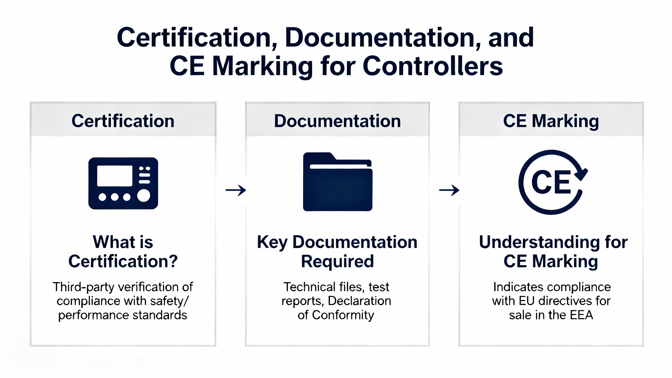
Certification, Documentation, and CE Marking for Controllers
From a regulatory standpoint, industrial controllers fall under the EU EMC Directive when placed on the European market. ComplianceGate describes the scope of this directive as covering a wide range of electrical and electronic equipment, including programmable logic controllers and power supplies, as long as they can either generate electromagnetic interference or be disturbed by it.
The directive defines essential requirements. Equipment must not generate electromagnetic disturbance above levels that prevent radio, telecom, and other equipment from operating as intended, and it must have adequate immunity to expected disturbances. For fixed installations, the directive also requires the use of good engineering practice and adherence to manufacturer instructions.
Using harmonized EN standards, including the EN 61000 series, gives manufacturers a presumption of conformity with these essential requirements. ComplianceGate notes that manufacturers can demonstrate conformity via internal production control using their own EMC assessment and documentation or, in some cases, through an EU‑type examination involving a notified body.
Technical documentation must be kept for a defined period and must describe the product and its design in enough detail to show compliance. That includes circuit descriptions, applied standards, calculations and assessments, and EMC test reports. A formal EU Declaration of Conformity must identify the product, list the applied directives and standards, and be signed by a responsible person. User instructions must explain how to use the equipment according to its intended purpose without compromising EMC performance, and the CE mark and traceability information must be affixed where required.
For industrial controller manufacturers, aligning controller EMC design and testing with EN 61000 from the start makes this documentation much easier to produce. For integrators and machine builders, requesting EN 61000‑based EMC documentation from controller vendors is a pragmatic way to reduce regulatory risk for the final machine.
Working with EMC Test Labs and In‑House Tools
Most controller manufacturers will eventually send hardware to accredited EMC labs. UL Solutions describes how such labs provide emissions and immunity testing, guided by standards like the EN 61000 series, CISPR standards for emissions, and other sector‑specific standards. They can also help tailor test plans to match the intended environment of the controller, whether that is a residential panel or a heavy industrial line.
Intertek highlights another dimension: on‑site EMC testing for large machinery. While this is more common for big installations than for individual controllers, it is relevant when controllers are tightly integrated into large machines that cannot be tested in a standard chamber. In those cases, labs bring EN 61000‑4 test capabilities into the plant, applying tests like electrostatic discharge, radiated RF, fast transients, surges, and power‑frequency magnetic fields directly to the operational installation.
In parallel, equipment such as programmable AC and DC sources described by Pacific Power and InfiniPower allows manufacturers and integrators to perform pre‑compliance EMC and power quality tests in their own labs. These tools can emulate harmonics, flicker, voltage dips, short interruptions, and other phenomena defined in EN 61000‑3 and EN 61000‑4‑11. Using them early catches weaknesses before formal testing.
From a project partner perspective, the most effective pattern is to combine in‑house pre‑compliance capability with strategic use of accredited labs. That keeps costs under control, minimizes surprises at the certification stage, and provides credible, independent evidence of EN 61000 compliance when customers or authorities ask for it.
Key EN 61000 Standards Relevant to Industrial Controllers
The following table summarizes the EN 61000 standards that most often show up on industrial controller datasheets and EMC test plans, based on the sources cited earlier.
| Standard | Scope and Relevance to Industrial Controllers |
|---|---|
| EN 61000‑6‑2 | Generic immunity for industrial environments; ensures controllers withstand industrial‑level ESD, RF, EFT, surge, dips, and magnetic fields. |
| EN 61000‑6‑4 | Generic emissions for industrial environments; limits what controllers and their supplies may inject into the industrial EM environment. |
| EN 61000‑6‑1 / ‑6‑3 | Immunity and emissions for residential, commercial, and light industrial sites; relevant when controllers are used in lighter environments. |
| EN 61000‑4‑2 | Electrostatic discharge immunity; validates robustness of panels, connectors, and housings against operator and tool ESD. |
| EN 61000‑4‑3 / ‑4‑6 | Radiated and conducted RF immunity; ensures controllers tolerate RF fields and disturbances on cables from nearby wireless and power equipment. |
| EN 61000‑4‑4 / ‑4‑5 | Fast transient and surge immunity; tests robustness against switching noise and high‑energy surges on power and I/O lines. |
| EN 61000‑4‑8 | Power‑frequency magnetic field immunity; important for controllers mounted near high‑current conductors or transformers. |
| EN 61000‑4‑11 | Voltage dips, short interruptions, and variations on AC inputs; proves that controllers ride through or fail safely during grid anomalies. |
| EN 61000‑3‑2 / ‑3‑12 | Harmonic current limits; relevant for controllers with significant internal power conversion connected to public low‑voltage systems. |
| EN 61000‑3‑3 / ‑3‑11 | Limits on voltage changes, fluctuations, and flicker; protect the public grid from disturbance caused by connected equipment. |
When you see a controller’s EMC declaration include these standards with appropriate performance criteria, you know you are dealing with a device designed and tested for real industrial life.
A Practical Mindset for Project Teams
For project teams selecting and deploying industrial controllers, the most practical mindset is to treat EN 61000 compliance as a shared responsibility between the controller vendor and the integrator.
On the vendor side, controllers should be designed and tested against the appropriate EN 61000 standards for the intended environment, with clear documentation of test levels, performance criteria, and any required external protection or installation practices. Vendors should be prepared to share EMC test reports and explain how they interpret performance criteria A, B, and C for their products.
On the integrator side, panel design, wiring, grounding, and overall machine layout must respect the assumptions in those test reports. Cables should be routed and shielded as recommended. Protective devices and filters specified in the manuals should be installed. Where possible, pre‑compliance checks should be run on critical panels or machines, especially when they combine multiple high‑power and high‑speed systems.
Treating EN 61000 as a living design constraint rather than a checklist item at the end keeps risks manageable. The standards provide a common language for vendors, integrators, and test labs to collaborate on robust, predictable behavior, rather than reacting to field failures under schedule pressure.
Short FAQ
Does EN 61000 certification guarantee my controller will never have EMC problems in the field?
No. EN 61000 certification shows that the controller met defined emission and immunity requirements under specified test setups and performance criteria. Real installations can differ in wiring length, grounding, and nearby equipment. You still need good engineering practice at the system level and, in demanding cases, in‑situ testing to verify the complete installation.
What is the difference between EN 61000‑6‑1 and EN 61000‑6‑2 for controllers?
Both are generic immunity standards, but they target different environments. EN 61000‑6‑1 is for residential, commercial, and light‑industrial environments with generally lower disturbance levels, while EN 61000‑6‑2 is for heavy industrial environments with stronger interference. For controllers intended for factories and process plants, EN 61000‑6‑2 is usually the more relevant benchmark.
If my controller is EN 61000‑compliant, why do I still need documentation and a Declaration of Conformity?
Under the EMC Directive, compliance is not just about test results. Manufacturers must keep technical documentation that shows how the product meets the essential requirements and must issue a Declaration of Conformity that references the applied standards. This documentation, together with CE marking and proper user instructions, is what gives legal access to EU markets and provides traceability for customers and regulators.
Closing
Industrial controllers that carry serious EN 61000 EMC credentials earn their keep every time a drive starts, a welder fires, or the grid sags and your line keeps running. From a systems integrator’s perspective, choosing such controllers and installing them according to sound EMC practice is one of the most cost‑effective ways to buy reliability. Treat the standards as a design partner, not a hurdle, and they will quietly protect your projects long after the factory acceptance test is over.
References
- https://www.can-cia.org/fileadmin/cia/documents/proceedings/1999_pinker_skala_kosturik.pdf
- https://www.plctalk.net/forums/threads/checklist-for-complying-with-en-61000-6-industrial-emc.148210/
- https://www.academyofemc.com/emc-standards
- https://www.assured-systems.com/understanding-en-50155-emc-standards-and-e-mark-certification-a-comprehensive-guide/
- https://resources.system-analysis.cadence.com/blog/msa2021-ensuring-emc-in-industrial-electronics
- https://www.celectronics.com/learning-center/residential-commercial-and-light-industrial
- https://www.compliancegate.com/emc-directive/
- https://incompliancemag.com/emc-compliance-in-industrial-equipment/
- https://www.infinipowertech.com/iec-61000-4-11-and-emc-immunity-test/
- https://keystonecompliance.com/iec-61000-6-general/
Keep your system in play!
Top Media Coverage
Categories


Related Products
-
 TZIDC Digital PositionerManufacturer: ABB
 -
 3300 Xl Nsv Photoelectric ProbeManufacturer: Bently Nevada
 -
3300 XL 8 mm Proximity ProbesManufacturer: Bently Nevada
-
 High Frequency Switching RectifierManufacturer: Emerson
 -
FLEXEX I/O OUTPUT MODULEManufacturer: Allen-Bradley
-
 ANALOG OUTPUT MODULEManufacturer: General Electric
 -
Velomitor CT Velocity TransducerManufacturer: Bently Nevada
-
 DUAL MEDIA EXTERNAL ADAPTERManufacturer: Allen-Bradley
 -
 DIGITAL HYGROMETERManufacturer: Panametrics
 -
3300 XL 8 mm Proximity ProbesManufacturer: Bently Nevada

Related articles Browse All
-
 amikong NewsSchneider Electric HMIGTO5310: A Powerful Touchscreen Panel for Industrial Automation2025-08-11 16:24:25Overview of the Schneider Electric HMIGTO5310 The Schneider Electric HMIGTO5310 is a high-performance Magelis GTO touchscreen panel designed for industrial automation and infrastructure applications. With a 10.4" TFT LCD display and 640 x 480 VGA resolution, this HMI delivers crisp, clear visu...
 -
 BlogImplementing Vision Systems for Industrial Robots: Enhancing Precision and Automation2025-08-12 11:26:54Industrial robots gain powerful new abilities through vision systems. These systems give robots the sense of sight, so they can understand and react to what is around them. So, robots can perform complex tasks with greater accuracy and flexibility. Automation in manufacturing reaches a new level of ...
 -
 BlogOptimizing PM Schedules Data-Driven Approaches to Preventative Maintenance2025-08-21 18:08:33Moving away from fixed maintenance schedules is a significant operational shift. Companies now use data to guide their maintenance efforts. This change leads to greater efficiency and equipment reliability. The goal is to perform the right task at the right time, based on real information, not just ...


- Q&A
- Policies How to order Part status information Shipping Method Return Policy Warranty Policy Payment Terms
- Asset Recovery
- We Buy Your Equipment. Industry Cases Amikong News Technical Resources Why choose us
- ADDRESS
-
 32D UNITS,GUOMAO BUILDING,NO 388 HUBIN SOUTH ROAD,SIMING DISTRICT,XIAMEN
Leave Your Comment