
-
Please try to be as accurate as possible with your search.
-
We can quote you on 1000s of specialist parts, even if they are not listed on our website.
-
We can't find any results for “”.
EMI/EMC‑Certified Industrial PCs: The Quiet Backbone of Reliable Automation
Electromagnetic compatibility is one of those topics that rarely shows up in glossy project slides, but it will absolutely show up in your downtime statistics. The industrial PC at the heart of your line is sitting in the middle of a storm of motors, drives, welders, radios, and switching power supplies. If that PC is not designed and certified for electromagnetic compatibility, you are relying on luck rather than engineering.
From the perspective of a systems integrator, an EMI/EMC‑certified industrial PC is not a luxury feature. It is a control risk you either actively manage or quietly accept. In this article, I will unpack what EMI and EMC mean in practice, what “certified” really covers, how these PCs are tested, and how to specify and integrate them so your automation system keeps running when the electrical environment gets ugly.
EMI, EMC, and EMS in Plain Language
Electromagnetic interference, or EMI, is unwanted electromagnetic energy that disrupts the operation of electronic equipment. Sources can be natural, such as lightning and solar activity, or man‑made, such as switch‑mode power supplies, variable‑frequency drives, welding machines, industrial inverters, radios, and wireless networks. As compliance specialists like Premier Filters and E‑Micrologix point out, this interference can be radiated through the air or conducted along power and signal cables.
Electromagnetic compatibility, or EMC, is the flip side. It is the ability of a device to function correctly in its electromagnetic environment without being disturbed by surrounding EMI and without itself causing excessive interference. Organizations such as Nemko and BVM describe EMC as a balance between emissions and immunity. Emissions are the electromagnetic noise your device puts out. Immunity is how resistant your device is to external disturbances.
You will also see the term electromagnetic susceptibility, often abbreviated EMS. This refers specifically to how susceptible a piece of equipment is to interference from the outside world. EMC testing covers both sides of the equation. EMI tests check that emissions stay below limits, while EMS or immunity tests check that the product keeps working when exposed to electrostatic discharge, fast transients, surges, and radio‑frequency fields.
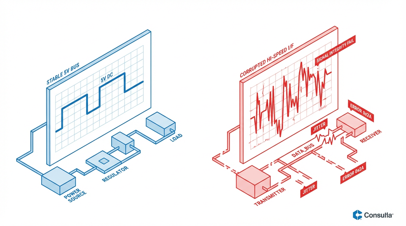
Modern industrial PCs and controllers are more vulnerable to EMI than older gear because their clocks run in the multi‑gigahertz range and their logic operates at lower voltages. As EMC Dorexs notes for computing systems in general, that combination makes digital signals easier to disturb. A short spike that would have been ignored on a five‑volt bus can flip bits on a low‑voltage high‑speed interface.
Why Industrial PCs Need Robust EMC
Industrial environments are electrically noisy by definition. According to BVM and Rocket PCB, typical sources of EMI on the plant floor include high‑current switching circuits in power converters, large motors and drives, welding equipment, and dense clusters of wired and wireless communication equipment. On top of that, you have long cable runs, shared grounds, and big metal structures acting as antennas.
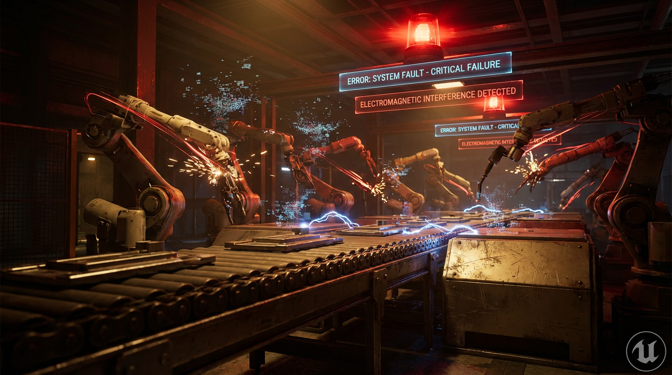
When an industrial PC with poor EMC shares that environment, several failure modes become likely. You can see corrupted data from sensors and encoders, intermittent network errors, spurious alarms, or an HMI that locks up when a nearby drive starts. E‑Micrologix and EMC Dorexs describe these symptoms in broader computing contexts, from random crashes and packet loss to display flicker and storage errors. On an automated line, the same phenomena can trigger downtime, quality issues, and safety trips.
The business impact is real. EMC Dorexs notes that downtime in critical computing environments can cost on the order of thousands of dollars per minute. Industrial automation is no different. A line that stops unexpectedly because an uncertified PC reset during an electrostatic event is more than a technical nuisance; it is an avoidable hit to throughput, labor efficiency, and delivery promises.
EMC is also a legal obligation. In the United States, FCC Part 15 regulates radio‑frequency emissions for almost all electronic devices before they can be marketed. In Europe, the EMC Directive and, for radio products, the Radio Equipment Directive define compatibility requirements. Compliance specialists like Compliance Testing and Astrodyne TDI emphasize that passing EMI and EMC testing is a prerequisite for market access. OnLogic makes the point that certifications such as CE and FCC should be treated as core design principles rather than after‑the‑fact paperwork.
For industrial PCs, this means that EMC is not just about being a good neighbor in the RF spectrum.
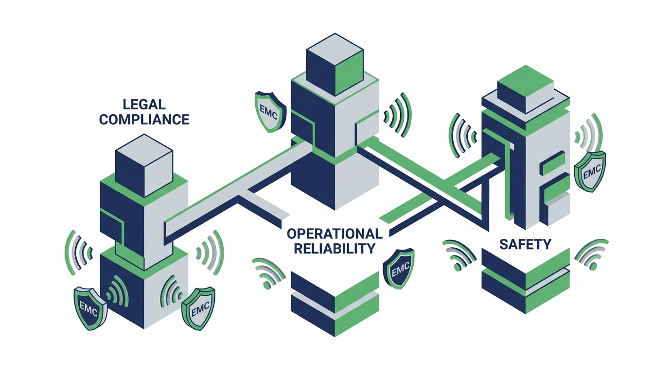
It is the foundation of legal market access, operational reliability, and safety, especially when your systems share space with other critical equipment.
What “EMI/EMC‑Certified Industrial PC” Actually Means
An EMI/EMC‑certified industrial PC is not just a rugged office PC with a badge on the front. According to PSB Engineering, an EMC‑certified industrial PC is engineered from the ground up and lab‑verified to meet strict electromagnetic compatibility standards in demanding industrial and medical environments. In German standards language this is often called EMV, short for elektromagnetische Verträglichkeit, but the concept is the same.
These systems are designed to do two things at once. They must keep emissions low, so they do not pollute the electromagnetic environment, and they must exhibit high interference immunity so they keep operating when exposed to external fields, static discharges, and power disturbances. That dual goal is implemented through enclosure shielding, grounding schemes, filtered interfaces, and careful PCB and cable design.
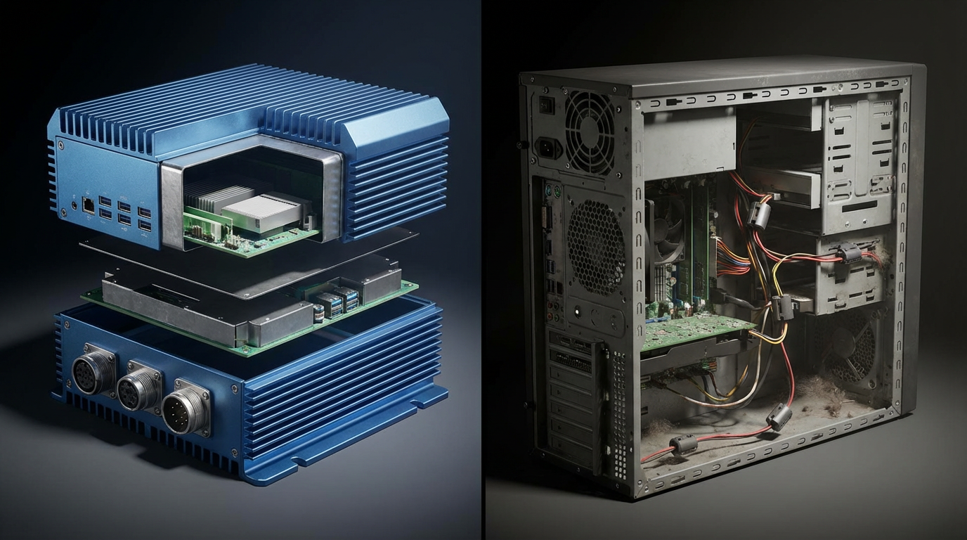
Compared with an office PC, the certified industrial PC typically has a sealed or shielded enclosure, shielded and filtered I/O connectors, industrial‑grade power‑supply filtering, and a PCB layout that controls loop areas and return paths to minimize EMI. BVM highlights similar measures in its industrial PC designs, including robust shielding, proper grounding and bonding, and carefully planned component placement and routing.
From a regulatory perspective, “certified” usually implies documented compliance with region‑specific standards and often with sector‑specific requirements.
Core EMC Certifications and Standards
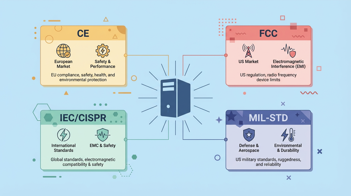
In Europe, the CE marking is the umbrella symbol that an industrial PC meets essential safety, health, and environmental requirements, including EMC. PSB Engineering notes that EMC‑tested industrial PCs are validated against standards such as DIN‑EN 61000‑6‑7 for industrial environments and, for medical applications, EN 60601‑1 and related EMC clauses. Technical documentation includes formal test reports, a technical file, and an EU Declaration of Conformity.
In the United States, FCC Part 15 regulates unintentional radiators, which covers most industrial PCs. Compliance Testing and Nemko describe how devices are placed in controlled test environments, such as anechoic chambers, and evaluated against limits on both conducted emissions on power lines and radiated emissions through the air.
Internationally, many countries reference IEC and CISPR standards. Examples from the research include CISPR 11 and CISPR 22 for radio interference limits, EN 55032 for multimedia equipment emissions, and the IEC 61000‑4 series for immunity tests such as electrostatic discharge, radiated immunity, and electrical fast transients. Premier Filters and E‑Micrologix emphasize that accredited labs use standardized methods, calibrated equipment, and qualified sites that conform to these standards.
For specialized sectors, additional requirements apply. OnLogic points to ATEX for explosive atmospheres, EN 50121‑3‑2 for railway EMC, and various hazardous‑location approvals. In medical environments, regulators require compliance with standards such as IEC 60601‑1‑2 for EMC. In military and certain hazardous industrial applications, MIL‑STD‑461 and MIL‑STD‑464 define more stringent EMI/EMC performance and system‑level compatibility, as described by Intrinsically Safe Store.
The result is that a properly certified industrial PC does not just claim to be rugged.

It comes with formal evidence that its emissions and immunity have been verified against recognized norms.
A Quick Comparison of EMC Regimes
The table below summarizes some key EMC frameworks that often come up in industrial PC projects.
| Regime or standard | Typical scope for IPCs | Primary focus | Notes for integrators |
|---|---|---|---|
| CE (EU EMC Directive) | Industrial and medical PCs sold in Europe | Emissions and immunity in industrial use | Requires technical file and Declaration of Conformity; often references IEC 61000. |
| FCC Part 15 (USA) | Unintentional radiators, including industrial PCs | Radiated and conducted emissions | Mandatory for U.S. market access; emissions driven but still tied to reliability. |
| IEC / CISPR standards | Global baseline for EMI/EMC testing | Emissions and immunity methods and limits | Adopted or referenced by many national regulators worldwide. |
| MIL‑STD‑461 / 464 | Military and hazardous industrial systems | Stringent emissions and susceptibility limits | More severe conditions; used when failure consequences are especially high. |
When you specify an industrial PC, you should know which of these regimes apply to your project and insist that the vendor provide current test reports or declarations that map to them.
How EMI/EMC Testing Is Actually Done
EMI and EMC can sound like “dark magic” to non‑specialists, but the test process is systematic. Virginia Tech’s Center for Power Electronics notes that EMI analysis and solutions are grounded in clear theory and practical examples, not guesswork. For industrial PCs, the process typically combines pre‑compliance testing during development with full compliance testing at an accredited lab.
Emissions Testing: What the PC Puts Into the Environment
Emissions testing measures the electromagnetic noise generated by the industrial PC to ensure it stays below defined limits. Compliance Testing, Premier Filters, and E‑Micrologix all describe similar methodologies.
For radiated emissions, the PC is placed in an environment such as an anechoic chamber designed to absorb reflections. Calibrated antennas and spectrum analyzers are used to measure the energy the PC radiates over a range of frequencies, often while running a worst‑case workload. The goal is to confirm that the PC will not interfere with nearby equipment, from radios and Wi‑Fi to sensitive instruments.
For conducted emissions, the focus is on noise traveling along power and signal cables. Line Impedance Stabilization Networks, or LISNs, are inserted between the PC and the power source. They provide a stable, known impedance and allow measurement instruments to capture the conducted noise. Premier Filters uses such pre‑compliance tests to determine filtering needs, and E‑Micrologix notes that they are essential to verify that disturbances on power lines will not disrupt other devices.
Immunity Testing: How the PC Survives in a Noisy World
Immunity testing reverses the perspective. Instead of asking “how loud is this PC,” the question becomes “how well does this PC cope with interference around it.” Standards organizations such as IEC define several key test types.
Electrostatic discharge testing, often following IEC 61000‑4‑2, subjects the system to controlled static discharges at various points on the enclosure and connectors. CESI IPC highlights test levels of 6 kV contact discharge and 12 kV air discharge as strong indicators that an industrial PC can maintain stable operation under severe static conditions, such as dry air and frequent operator contact.
Electrical fast transient and surge tests, such as those defined in IEC 61000‑4‑4 and related standards, simulate rapid voltage spikes and bursts on power and signal lines, similar to what you see when large inductive loads switch. Radiated and conducted immunity tests expose the PC to external RF fields and disturbances on cables, verifying that it continues to perform its intended functions.
During these tests, the PC is monitored for functional degradation, data errors, resets, and lockups. BVM and Astrodyne TDI emphasize that true EMC testing is not just about survival. The device must keep operating correctly without suffering unacceptable disturbance.
Pre‑Compliance vs. Formal Compliance
An important practical distinction is between pre‑compliance testing and full compliance testing. Pre‑compliance testing is early‑stage evaluation using in‑house or local setups to catch gross EMI/EMC issues before sending hardware to an accredited lab. Revine Technologies and Tektronix both describe how relatively modest setups combining spectrum analyzers, near‑field probes, LISNs, and simple chambers can identify hot spots and weak points.
This stage is where PCB layout changes, grounding adjustments, shielding tweaks, and filter selections are refined. Tektronix’s EMCVu solution, for example, automates scanning, reporting, and ambient noise calibration to streamline this phase. Using pre‑compliance tools allows designers to iterate quickly, reducing the risk of failing expensive formal tests.

Formal compliance testing is then carried out at accredited labs, such as those certified to ISO/IEC 17025, as noted by Astrodyne TDI and E‑Micrologix. These labs perform standardized tests, generate detailed reports, and provide the evidence required for CE marking, FCC certification, and other approvals. Skipping pre‑compliance often leads to failures at this stage, forcing redesigns, repeated lab campaigns, and schedule slips.
For a systems integrator, the key takeaway is that a vendor who invests in rigorous pre‑compliance and formal EMC testing will usually deliver industrial PCs that behave predictably on your plant floor.
Design Practices Behind EMC‑Certified Industrial PCs
Robust EMC performance does not come from a single magic component. It is the result of discipline across enclosure design, PCB layout, power architecture, and cabling.
PSB Engineering points to EMV‑compliant enclosures that use specialized shielding, grounding, and layout techniques to mitigate EMI risks. This includes gasketed seams, conductive coatings, and carefully treated ventilation paths so the enclosure behaves like a Faraday cage rather than an RF antenna.
BVM describes EMC‑conscious industrial PC design as rooted in robust shielding, proper grounding and bonding, and selection of EMC‑compliant components. PCB design practices borrowed from high‑speed electronics are central. ProtoExpress outlines several of these, such as keeping signal return paths short over solid ground planes to minimize loop area, controlling impedance for high‑speed nets to avoid reflections, separating sensitive traces like clocks and resets from noisy lines, and minimizing vias on critical routes to reduce parasitic inductance and radiation.
Rocket PCB emphasizes that in industrial PCBs, internal switching noise from ICs and external noise from the environment must be simultaneously managed. That means combining filtering on power lines, careful trace routing to avoid crosstalk, and well‑planned ground strategies. Good EMC design also pays attention to cable entry points, connector pinouts, and the interface between PCB and enclosure ground.
Environmental sealing often works in tandem with EMC measures. OnLogic explains how IP65 and IP67 ratings define resistance to solids and liquids. IP65 enclosures are dust‑tight and protected against low‑pressure water jets, while IP67 units can withstand immersion in water to about 3.3 ft for a limited time. Many EMC‑certified industrial PCs combine sealed, fanless designs with shielding so they can operate in dusty, wet, or wash‑down environments without fans introducing dust or acting as additional EMI sources.
Front‑end displays are another crucial interface. Rocktech notes that EMI‑shielded LCDs integrate conductive films or layers that block or redirect interference, preventing flicker, image noise, and touch malfunctions in high‑noise settings such as factories, vehicles, and medical systems. In an HMI panel, this display layer is part of the overall EMC behavior of the PC.
For integrators, the practical point is that all these measures are far easier and more reliable to implement in a purpose‑designed industrial PC than as retrofits to a generic office system.
Why Retrofitting EMC Is Rarely Enough
Almost every integrator has at some point tried to quiet a noisy system by adding ferrite cores, retrofitting shielded housings, or bolting on external filters. PSB Engineering acknowledges that retrofits such as shielded housings, filtered power supplies, and improved grounding can reduce EMI. E‑Micrologix also notes that adding line filters and ferrites can help existing installations.
However, both experience and the research emphasize that retrofits rarely achieve the robustness of a system designed and tested for EMC from the beginning. Retrofits usually target symptoms rather than root causes. They may lower emissions at specific frequencies without fully addressing susceptibility, or they may work only under certain cable routings and loading conditions.
More importantly, retrofitted systems typically lack formal, system‑level test evidence. They might behave acceptably in your plant today but have no documented margin against future changes, such as adding a new wireless system or reconfiguring power distribution. When you select an industrial PC that was engineered for EMC, tested to recognized standards, and accompanied by current reports, you are buying predictable behavior rather than a collection of patches.
In my view, retrofits make sense for troubleshooting and incremental improvement in existing installed bases. For new projects or major line upgrades, the better strategy is to start with properly certified industrial PCs and build the rest of the system around that foundation.
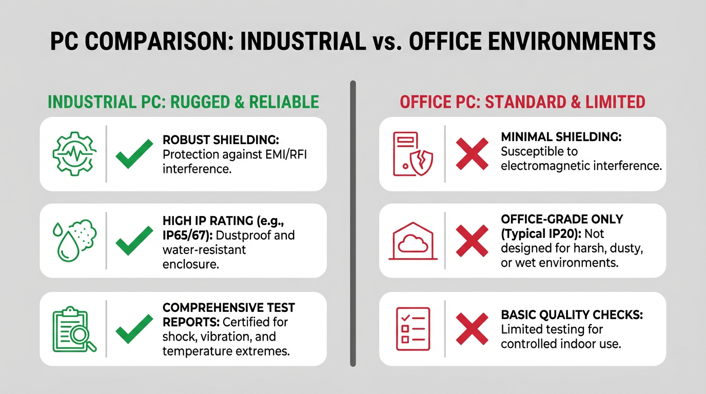
Certified Industrial PCs vs. Office PCs in Automation
It can be tempting to specify an inexpensive office PC for light‑duty tasks such as basic HMI or data logging. To understand the risk, it is useful to compare how a certified industrial PC differs from a general‑purpose office system.
| Aspect | EMI/EMC‑certified industrial PC | General office PC |
|---|---|---|
| EMC design goal | Low emissions and high immunity in harsh, electrically noisy sites | Meets office‑grade emissions limits; immunity not industrial‑grade |
| Enclosure and shielding | Shielded, often sealed metal housings with EMC gaskets and filters | Ventilated cases with minimal RF shielding |
| Power and I/O | Filtered, often isolated interfaces and industrial‑grade connectors | Consumer power supplies and connectors with limited filtering |
| Environmental protection | Frequently rated at IP65 or higher; designed for vibration and dust | Designed for climate‑controlled offices |
| Test and certification evidence | Formal EMC reports, technical file, declarations for CE/FCC and more | Often only basic FCC or equivalent emissions self‑declaration |
| Life cycle and support | Long‑term availability, consistent BOM for validated designs | Frequent model changes without EMC re‑validation for your use case |
BVM, OnLogic, and PSB Engineering all position their industrial PC offerings around these differences. When you integrate such systems into automation, you gain not just robustness against EMI but also a stable hardware platform available for many years, which matters when EMC testing and validation are part of your project cost.
How to Specify an EMI/EMC‑Certified Industrial PC
From a systems integrator’s standpoint, the right way to handle EMC is to treat it as a design requirement from day one, not an afterthought during factory acceptance tests.
Start by clarifying the regulatory context of your project. If the machine or line needs CE marking, then the industrial PC must support compliance with the EMC Directive and any sector‑specific standards such as EN 60601‑1‑2 for medical equipment or ATEX rules for explosive atmospheres. For projects bound for North America, confirm that the PC is tested to the relevant FCC Part 15 category and, where applicable, to industry‑specific EMC standards for that sector.
Next, define the electromagnetic environment. A clean laboratory or electronics assembly line is different from a welding bay or a chemical plant with large pumps and compressors. Rocket PCB notes that typical industrial EMI sources include high‑current switching circuits, power converters, motors, wired and wireless communication systems, and external towers or neighboring facilities. Sharing this context with your PC vendor helps them recommend an appropriate platform and, if necessary, higher‑severity EMC options or even MIL‑grade designs where the risk justifies the cost.
When evaluating industrial PCs, ask vendors to provide recent EMC test reports and declarations, not just marketing claims. PSB Engineering emphasizes that compliant systems come with documented evidence of tests against standards such as EN 55032, IEC 61000‑4‑2, and IEC 61000‑4‑4. CESI IPC highlights ESD robustness at levels such as 6 kV contact and 12 kV air discharge. These numbers matter when you are planning for dry winter air, operators touching metal bezels, and frequent plugging and unplugging of USB or serial devices.
Consider how the PC will be integrated mechanically and electrically. An EMC‑certified PC can still be compromised by poor panel wiring. Keep noisy power cables separated from sensitive signal and communication lines, use shielded cables where appropriate and terminate shields correctly, and follow sound grounding practices to avoid ground loops. Research from ProtoExpress and E‑Micrologix underscores the importance of controlled return paths and avoiding unintended antennas in the form of long, unshielded conductors.
Review the whole system’s certification strategy. OnLogic warns that missing certifications can cause late‑stage rework, safety risks, and regulatory problems. If the industrial PC is already EMC‑certified, you are starting from a strong baseline. The rest of the panel, including power supplies, I/O modules, and drives, should be selected with compatible EMC performance in mind. Where possible, choose components whose EMC behavior has been verified under conditions similar to your project.
Finally, treat EMI/EMC pre‑compliance testing as a strategic tool rather than a last‑minute check. Revine Technologies and Tektronix both show that early in‑house testing with spectrum analyzers, near‑field probes, and software tools allows you to identify and fix major issues well before formal certification. For integrators, that might mean working with OEMs or test labs to run quick scans on the integrated panel, verifying that combining a particular PC, drive, and I/O configuration still leaves margin relative to limits.
Brief FAQ
Q: Do I really need an EMI/EMC‑certified industrial PC if the rest of my panel already carries a CE mark? A: The CE mark applies to the complete system placed on the market, not just one component. If you substitute an uncertified office PC into a panel that was originally evaluated with an EMC‑tested industrial PC, you change the system’s emissions and immunity in ways that were not covered by the original assessment. Selecting an industrial PC with documented EMC compliance helps keep the overall system within its intended performance envelope and simplifies your justification during audits or investigations.
Q: What EMC test levels should I look for in industrial PCs? A: Formal requirements depend on the standards that apply, but there are useful reference points. CESI IPC points to electrostatic discharge levels of 6 kV contact and 12 kV air discharge under IEC 61000‑4‑2 as evidence of strong static robustness. Standards such as EN 55032 and the IEC 61000‑4 series define emissions and immunity methods and limits for typical industrial environments. When talking with vendors, ask which specific standards and test levels their PCs have passed and request the corresponding reports.
Q: When is it worth specifying MIL‑STD‑461‑tested equipment for an industrial project? A: Intrinsically Safe Store describes MIL‑STD‑461 and related military EMC standards as more stringent and suited for harsh, hazardous environments such as defense, aerospace, and oil and gas operations, where failures could be catastrophic. In general industrial automation, commercial EMC standards are adequate and more cost‑effective. MIL‑grade EMC is worth considering when the environment is extremely severe or when system failure carries disproportionate safety, environmental, or mission risk.
In the end, EMI/EMC‑certified industrial PCs are one of the quietest risk reducers you can specify. They do not make your line faster by themselves, but they make it far more likely that the line will still be running when the motors, drives, radios, and welders are all screaming around it. Treat EMC as a design requirement, choose certified hardware, and you turn electromagnetic chaos from a source of surprises into an engineered part of your control strategy.

References
- https://pe.gatech.edu/courses/emcemi-for-engineers-and-engineering-managers
- https://cpes.vt.edu/education/courses/emi_analysis_and_solutions_for_power_electronics
- https://calhoun.nps.edu/server/api/core/bitstreams/f4827d06-61ec-4ac5-a86c-34f79e4a7ab1/content
- https://www.emcdorexs.com/emi-in-computer-understanding-electromagnetic-interference-and-its-impact-on-computing-systems.html?srsltid=AfmBOoo2m3aXaBtYJWerv5YqSot-MRTEv4lXWfwGbyBHuXOgyS33xnsk
- https://revinetech.com/emi-emc-pre-compliance-testing
- https://www.rocket-pcb.com/ensuring-emi-emc-compliance-in-industrial-pcbs-what-are-the-key-design-considerations-for-electromagnetic-compatibility
- https://resources.altium.com/p/emi-and-emc-compliance-101-pcb-designers
- https://www.astrodynetdi.com/blog/the-importance-of-emi-and-emc-testing
- https://cesipc.com/why-industrial-pcs-must-pass-emc/
- https://compliancetesting.com/emi-testing/
Keep your system in play!
Top Media Coverage
Categories


Related Products
-
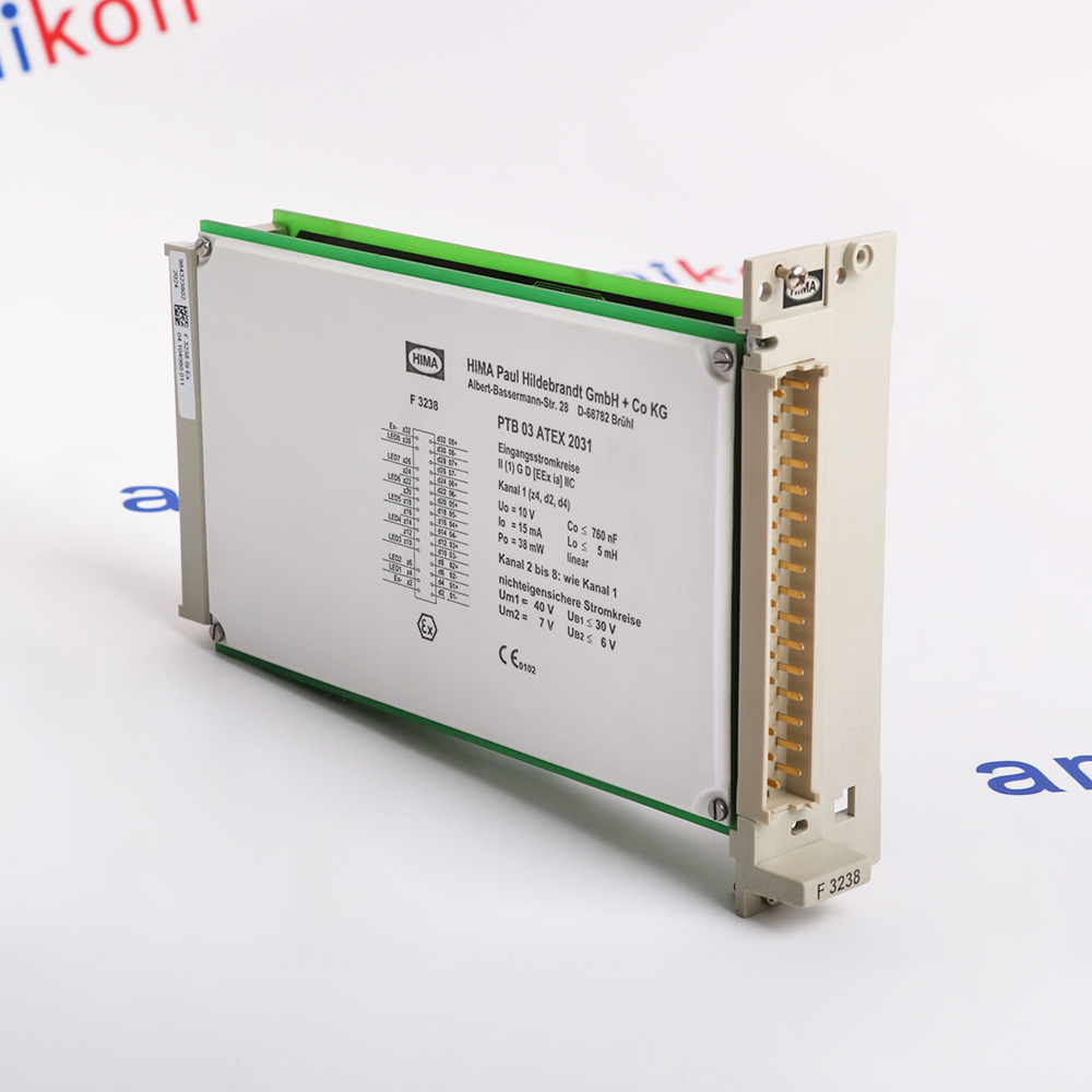 8 Channel Safety-Related Input ModuleIn StockManufacturer: HIMA
 -
 4-fold relay module, safety relatedManufacturer: HIMA
 -
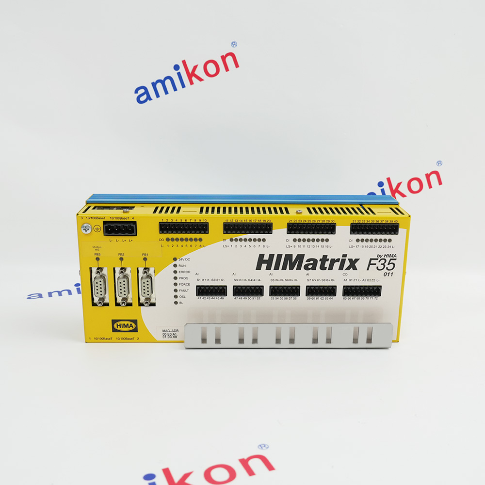 Safety-Related ControllerManufacturer: HIMA
 -
 Safety Remote Output ModuleManufacturer: HIMA
 -
CPU BoardManufacturer: HIMA
-
Ethernet communication moduleManufacturer: HIMA
-
SAFETY CENTRAL MODULEManufacturer: HIMA
-
4-Fold Fail-Safe Relay AmplifierManufacturer: HIMA
-
16-Channel Digital Input ModuleManufacturer: HIMA
-
Remote I/O ModuleManufacturer: HIMA

Related articles Browse All
-
 amikong NewsSchneider Electric HMIGTO5310: A Powerful Touchscreen Panel for Industrial Automation2025-08-11 16:24:25Overview of the Schneider Electric HMIGTO5310 The Schneider Electric HMIGTO5310 is a high-performance Magelis GTO touchscreen panel designed for industrial automation and infrastructure applications. With a 10.4" TFT LCD display and 640 x 480 VGA resolution, this HMI delivers crisp, clear visu...
 -
 BlogImplementing Vision Systems for Industrial Robots: Enhancing Precision and Automation2025-08-12 11:26:54Industrial robots gain powerful new abilities through vision systems. These systems give robots the sense of sight, so they can understand and react to what is around them. So, robots can perform complex tasks with greater accuracy and flexibility. Automation in manufacturing reaches a new level of ...
 -
 BlogOptimizing PM Schedules Data-Driven Approaches to Preventative Maintenance2025-08-21 18:08:33Moving away from fixed maintenance schedules is a significant operational shift. Companies now use data to guide their maintenance efforts. This change leads to greater efficiency and equipment reliability. The goal is to perform the right task at the right time, based on real information, not just ...


- Q&A
- Policies How to order Part status information Shipping Method Return Policy Warranty Policy Payment Terms
- Asset Recovery
- We Buy Your Equipment. Industry Cases Amikong News Technical Resources Why choose us
- ADDRESS
-
 32D UNITS,GUOMAO BUILDING,NO 388 HUBIN SOUTH ROAD,SIMING DISTRICT,XIAMEN
Leave Your Comment