-
Manufacturers
- ABB Advant OCS and Advant-800xA
- ABB Bailey
- ABB Drives
- ABB H&B Contronic
- ABB H&B Freelance 2000
- ABB Master
- ABB MOD 300, MOD 30ML & MODCELL
- ABB Procontic
- ABB Procontrol
- ABB Synpol D
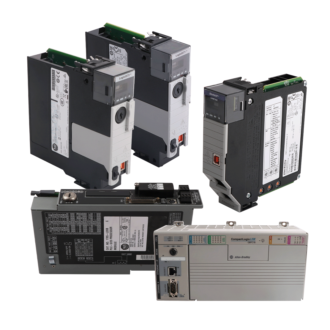
- Allen-Bradley SLC 500
- Allen-Bradley PLC-5
- Allen-Bradley ControlLogix
- Allen-Bradley CompactLogix
- Allen-Bradley MicroLogix
- Allen-Bradley PanelView
- Allen-Bradley Kinetix Servo Drive
- Allen-Bradley PowerFlex
- Allen-Bradley Smart Speed Controllers
- 21500 TDXnet Transient
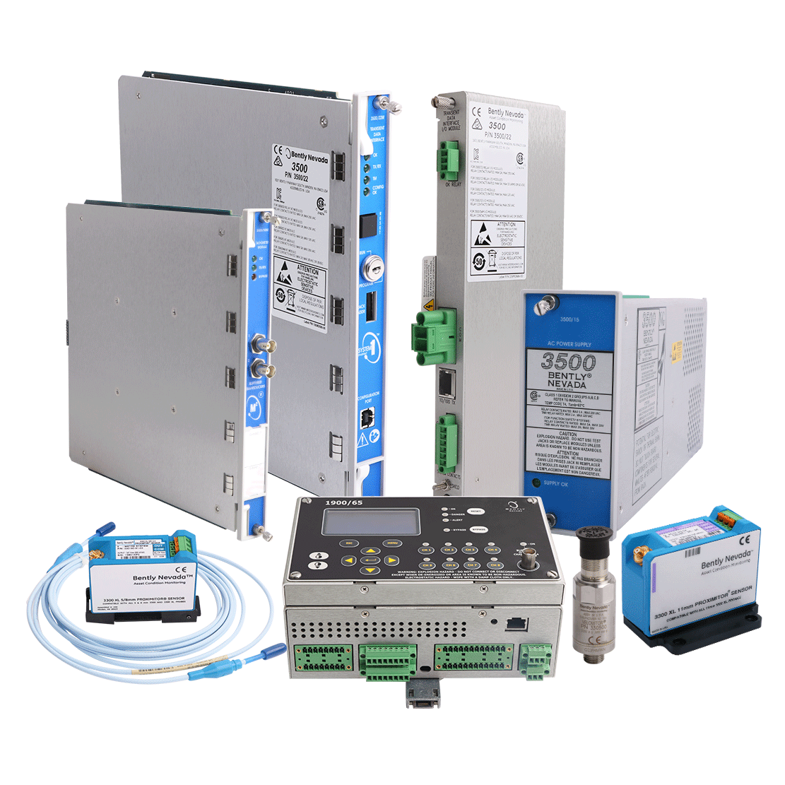
- 3300 System
- 3500 System
- 990 and 991 Transmitter
- 31000 and 32000 Proximity Probe Housing Assemblie
- 21000, 24701, and 164818 ProbeHousing Assemblies
- 177230 Seismic Transmitter
- TK-3 Proximity System
- 330500 and 330525 Piezo-Velocity Sensor
- 7200 Proximity Transducer Systems
- GE 90-70 Series PLC
- GE PACSystems RX7i
- GE PACSystems RX3i
- GE QuickPanel
- GE VersaMax
- GE Genius I/O
- GE Mark VIe
- GE Series One
- GE Multilin
- 800 Series I/O
- Modicon 984
- Modicon Premium
- Modicon Micro
- Modicon Quantum
- Telemecanique TSX Compact
- Altivar Process
- Categories
- Service
- News
- Contact us
-
Please try to be as accurate as possible with your search.
-
We can quote you on 1000s of specialist parts, even if they are not listed on our website.
-
We can't find any results for “”.
-
-
Get Parts Quote

All Manufacturers
-
Please try to be as accurate as possible with your search.
-
We can quote you on 1000s of specialist parts, even if they are not listed on our website.
-
We can't find any results for “”.
- bachmann
-
ABBAccutracAcopianAC TechAction InstrumentsAdamAdaptecAdvanced Input DevicesAdvanced Micro ControlsAEGAISAlcatelAllen-BradleyAllied Telesis3MAlstomAMCIAntex ElectronicsApparatebau HundsbachArray ElectronicAseaASTECAutomation DirectAydin ControlsB&RBalluffBanner EngineeringBarco SedoBartecBECKBeierBeijer ElectronicsBently NevadaBerthelBiviatorBlack BoxBlockBofors ElectronikBoschBraunBürkertBURLECanaryCarroll TouchCEAG3COMConracControlonCooper BussmannCooper Crouse-HindsCopes VulcanCromptonCrouzetControl TechniquesCTI-Control Technology IncCustom Servo MotorsCutler-HammerDanfossDaniel WoodheadDEC - Digital Equipment CorpDelta Computer SystemsDelta ElectronicsDevolDGD Gardner DenverDIA ElectronicDIGIDigitalDigitronicsDuragDynaparEATONEBELTEberleEchelonE. Dold & Söhne - DOLDEES Elelkra ElektronikEILeka TechnikElecktro-AutomatikElectronics Development Corp – EDCEletec ElektronicElliot AutomationElographicsEmersone-motionEndress HauserEntrelec SchieleEPIC DataERMAERO ElectronicEtherComESDESS StörcontrollerETSI - Electronic Technology SystemsEurothermFanucFarnellFEASFestoFinder VaritecFischer PorterForney EngineeringFOTEKFuji ElectricGalil Motion ControlGeneral ElectricGildemeisterGordosGrapha ElectronicGrayhillGrenzebach ElectronicsHartingHawaHedin TexHEIDENHAINHelmholzHerren ElectronicsHex Valve – RichardsHIMAHirschmannHitachiHitexHK SystemsHoneywellHorner - FACTSHüller HilleibaIBHsoftecIBMidecIDSIFM ElectronicINATINIVENIntelInvensysIPF ElectronicJAQUETJetter AGKentKEPCOKettnerKieback & PeterKlockner MoellerKnielKöster SystemtechnikKoyoKrauss MaffeiKuhnkeLambdaLandis GyrLauerL&N - Leeds & NorthrupLenzeLeukhardt SystemsLG GoldSecLiebherrLittlefuseLumbergLutzeMagnecraftMannesmannMatric LtdMatsushitaMDB SystemsMean WellMeasurement SystemsMeasurexMEDARMicro Innovation AGMicron Control TransformersMitsubishiMolexMoogMSC TuttlingenMTL Insturments GroupMTSMurr ElektronikMyers Power ProductsNAISNandi PowertronicsNECNetstalNeumannNiobrara R&DNobel ElektronikOmega EngineeringOmronOpto 22Orbitran SystemsPANALARMPenril Datability NetworksPepperl + FuchsPesterPhilipsPhoenix ContactPilzPlasmaPlüth EnergietechnikPotter & BrumfieldRamsey EngineeringRed LionReis RoboticsReliance ElectricRexrothRinck ElectronicRIS - RochesterRMPRobust Data CommRonanRWTSAE ElektronikSAIASATT ControlSauterSchad SinTecSchaffnerShawmut - Gould/FerrazSchieleSchildknechtSchiller ElectricSchleicherSchleuniger AGSchlicht + KüchenmeisterSchlumbergerSchneider ElectricSchrack TechnikSCM PC-CardSelectronSensyconSEWSigma Information SystemsSixnetSOHARDSorcusSpectrum ControlsSprecher + SchuhSPS TechnologiesSquare DStahlStandard MicrosystemsSTI - Scientific Technologies, Inc.StrombergStruthers-DunnSUTRON ElectronicSYNATEC ElectronicSyslogicSysMikTaylorTecnint HTETelemecaniqueTillquestTimontaToshibaTransition NetworksTR ElectronicUhlmannUnicompUniOPUnited SciencesVAHLEVan DornVibro-MeterVIPAVisoluxWachendorff AdvantechWagoWalcherWeberWeidmullerWenglorWestronicsWielandWöhrleWolfWoodwardWürth ElektronikYokogawaZebra TechnologiesZiehl-AbeggZollnerXycomEprobachmannSaftronicsSiemensKEBOpti MateAristaSankiDaiei KogyoshaBrooks CTI-CryogenicsMKSMatrixMotortronicsMetso AuttomationProSoftNikki DensoK-TEKMotorola VMEForce Computers IncBerger LahrICS TriplexSharp PLCYASKAWASCA SchuckerGrossenbacherHachMeltalBremerMolex WoodheadAlfa LavalSiemens RobiconPerkinsProfaceSupconCarlo GavazziDEASSTHollysysSOLIDSTATE CONTROLSETEKOPTEKKUKAWHEDCOindramatMiscellaneous ManufacturersTEKTRONIXRorzeDEIFSIPOSTICS TRIPLEXSHINKAWAANYBUSHVAGERMAN POWERKONTRONENTEKTELSYSTEMKOLLMORGENLAZERPRECISION DIGITALLUBRIQUIPINCNOKIASIEI-GefranMSA AUER MUTKEBAANRITSUDALSALoad SharerSICKBradSCHENCKSTAIGER MOHILOENTERASYSUSB-LGTRSBIOQUELLSCHMERSALCORECOKEYENCEBIZERBABAUERBAUERCONTROLPACIFIC SCIENTIFICAPPLIED MATERIALSNMBNIWeishauptWeinviewCISCOPARKERLenovoKONECRANESTURBULHMSHOFFMANHUTTINGERTDK-LambdaRESOLVERKnickATLASGAMXTDKCAMERONNSKTamagawaGIDDINGS & LEWISBENDERSABOWOODHEADFRICK YORKSHENLERBALDORLam ResearchNTN BEARINGETAWEST INSTRUMENTSTDK-LambdaSMCFireyeDAHUATESCHACROSSERFLUKESanyo DenkiBruel & KjaerEPSONHIOKIMettler ToledoRAYTEKEPCOSDFISEMIKRONHuaweiINDUSTRONICASI-HVEBARTEC POLARISAMATGD BolognaPrecise AutomationRADISYSZEISSReveal ImagingSaiernicoASEMASEMAdvantechANSALDOELproMARCONIEBMPAPSTROTORKKONGSBERGSOCAPELTAIYOSUNYorkKURODAADLINKNotifierHBMInfineonLNICSaipwellJIANGYIN ZHONGHEW.E.ST. ElektronikEXPODEEP SEA ELECTRONICSBECKHOFFBOMBARDIER TRANSPORTATIONDragerZENTRO ELEKTRONIKATOSTRSystemtechnikJDS UniphaseADEPTREOPanametricsXenusSIGMATEK DIASS.C.E ElettronicaEKFETELSTOBER POSIDYNHANSHINDDKEITZENBERGERLTI MOTIONXP PowerPanasonicMatroxSBS TechnologiesWARTSILAMURPHYMADOKAArcnet DanpexLittelfuseTACANHurcoSAMGONGALPHALuxcoNautibusPAWO SystemsHaver&boeckerVAISALAConsiliumSERIPLEXMTUALPHIOPTIMATION INCNTRONNIDECTMEIC GLOBALBAUMERSANYO-DENKISeicaISE ReiterSealICP ELECTRONICSAxiomtekBautzSonosysVaconNematronWatt DriveSieb & MeyerDanaher MotionDEMAGDigifasDivusBühlerRMV ELECTRONICSOno SokkiOrbotechPLATING ELECTRONICNORD NORDACDematicCircuit LineBergesAIENSNBAUMULLERSZMCHATILLONACS GROUPADVANTESTSekidenkoDOLDTURCKAPI ControlsASAHI KEIKIQUALIFLOWASMLASTROCOGNEXContecESTICFishmanIAITeleFrankInternixAUMAPROVIBTECHK-TRONLemforderIXYSALERTONMOXA
-
- Advant Controller 31 Advant Controller 110/160 Advant Controller 250 Master MOD 300 AC500 AC800F AC800M S100 I/O S200 I/O S400 I/O S800 I/O AC800F-Freelance S900 I/O 800PEC
- ACS 100 ACS 150 ACS 200 ACS 310 ACS 400 ACS 55 ACS 600 ACS 850 Stromberg ACS 140 ACS 160 ACS 300 ACS 355 ACS 500 ACS 550 ACS 800 DCS 800 Accessories ACS 580 ACS 1000 ACS880 MotiFlex e180 ACS 380
-
-
-
- MICROMASTER 1st Generation MICROMASTER 2nd Generation MICROMASTER 3rd Generation MICROMASTER 410/420/430/440 MICROMASTER Junior
- S5-090/095/100 S5-010 S5-101 S5-105 S5-110 S5-115 S5-130/150 S5-135/155 S5-210 S5 Memory S5 Simatic Net S5 Intelligent Processors S5 HMI S5 Batteries CPU100 CPU103 S5-150U CPU101 CPU110 S5-095U S5-135U (exc. PS) S5-155U (excl PS) CPU102 Moby S5-100U S5-150S rack
- C7 ET 200B ET 200C ET 200eco ET 200 ISP ET 200L ET 200M ET 200pro ET 200R ET 200S ET 200X M7-300 M7-400 S7 Simatic Net S7-1200 S7-200 S7-300 S7-400 S7-Batteries S7 HMI S7-Memory Simatic Box PC Simatic DP Simatic PG/Programming Simatic SC ET 200ISP ET 200SP S7-HMI Simatic Panel PC/Box PC Moby S7-1500 SITOP ET 200AL Simatic S7
All Categories
-
 Bus Expansion ModuleManufacturer: bachmann
 -
 CPU moduleManufacturer: bachmann
 -
 Six Channel Power AmplifierManufacturer: bachmann
 -
 Analog Input/Output ModuleManufacturer: bachmann
 -
 Memory CardManufacturer: bachmann
 -
 Industrial Ethernet SwitchManufacturer: bachmann
 -
 Memory CardManufacturer: bachmann
 -
 Vibration Sensor Input ModuleManufacturer: bachmann
 -
 Analog Input/Output ModuleManufacturer: bachmann
 -
 Digital I/O ModuleManufacturer: bachmann
 -
 I/O moduleManufacturer: bachmann
 -
 Analog In/Output ModuleManufacturer: bachmann
 -
 I/O MODULEManufacturer: bachmann
 -
 Digital I/O moduleManufacturer: bachmann
 -
 CPU moduleManufacturer: bachmann
 -
 pulse width modulation moduleManufacturer: bachmann
 -
 Analog In/Output ModuleManufacturer: bachmann
 -
 Operator PanelManufacturer: bachmann
 -
 Temperature Input ModuleManufacturer: bachmann
 -
 Processor ModuleManufacturer: bachmann
 -
 Digital input moduleManufacturer: bachmann
 -
 FASTBUS-ModulesManufacturer: bachmann
 -
 Analog Input ModuleManufacturer: bachmann
 -
 Processor moduleManufacturer: bachmann
 -
 CPU moduleManufacturer: bachmann

Bus Expansion Module
Bus expansion slave module
with 2 interfaces
Bus expansion slave module optionally
with integrated power supply
Up to 6 local substations
Minimal signal delay
Distances of up to 3 m between 2 stations
Integrated watchdog on slave modules
CPU module
CPU module MC212 (1,3GHz)
DualCore; 2GB DDR4; 512kB nvRAM;
2GB pSLC File-Flash;
2x Eth100/1000;
1xRS232;
1xRS232/422/485;
1xUSB3.0;
TPM;
CFast-Slot
4GB CFast Card
Cold Climate
Six Channel Power Amplifier
CPU Modul MC206 (600 MHz) SingleCore
1 GB DDR4
512 kB nvRAM
2 GB pSLC File-Flash
2x Eth100/1000
1x RS232
1x RS232/422/485
1x USB3.0
TPM
CFast-Slot
Analog Input/Output Module
Analog voltage input ±10 V to ±10 mV
Analog current input 0(4) to 20 mA
Temperature sensor Pt elements as 2-,3-,4-wire
Thermo couples type J, K, T, N, E, R, S, B
Analog voltage output ±10 V
Analog current output 0(4) to 20mA
Resolution: 16-bit input with filter, 14-bit output
Galvanic isolation from the system 500 V
Memory Card
Product:CFast Cards
Memory Size: 4 GB
Brand:Apacer
Packaging:Tray
Product Type:Memory Cards
Industrial Ethernet Switch
4 safety inputs for 4 to 20 mA signals
forming 2 logic safety channels
Optional encoder supply via the module
4 safety inputs for temperature measurement (Pt100)
forming 2 logic safety channels
2 safety inputs for strain gauge signals
forming one logic safety channel
Memory Card
Memory capacity 32/64 MB
Access width 16 bits
Designed as 5 V card
Program voltage of 12 Vss
Write protection via operating software
Vibration Sensor Input Module
Channels 10-12 can be
used as an analog input of ±10 V
Analog inputs individually
configurable for sensitivity
24 bit A-D resolution with a
dynamic range ≥ 96 dB
Adjustable sampling
rate up to 51.2 kHz
Adjustable analog and digital filtering
Analog Input/Output Module
8 channels AIO208, 16 channels AIO216
Analog inputs and outputs
Filter adjustable from 4 kHz to 0.5 Hz per channel
All outputs overload, short circuit and external voltage-proof
Measuring range monitoring freely adjustable (±105 %)
Error message on overload and overtemperature and undervoltage of the supply
Galvanic isolation from the system 500 V
Modes that can be selected per channel:
Analog voltage input ±10 V to ±10 mV
Analog current input 0(4) to 20 mA
Digital I/O Module
16 / 32 digital channels
16 channels can be configured as input or output
Configurable interrupt inputs
Status display for each channel via LED
Supply voltage 18 to 34 VDC
Supply voltage protected against reverse polarity
Cost effective and space saving
I/O module
Head module for CANopen slave stations
Up to 30 I/O modules per slave station
Optional integrated power supply
Transfer rate 10 Kbaud to 1 Mbaud
Bus length to 5000 m (signal repeater required)
Two internally connected CAN interfaces for loop-through of the cable
Galvanic isolation between CAN interfaces and control electronics
Node address can be set via rotary switch
Analog In/Output Module
8 analog inputs
8 analog outputs
Connection possibility single-ended or differential
Power supply for up to 4 potentiometers
Temperature inputs for up to 4 Pt100/Pt1000 sensors
2-wire or 4-wire inputs for Pt100/Pt1000 sensors
Wire break detection for the inputs (for voltage and temperature)
Short circuit proof outputs
Digital I/O module
compact CAN slave module
16/32 channels can be freely configured as input or output
Digital outputs each with 1 A continuous current
Two internally connected CAN interfaces for loop-through of the cable
Galvanic isolation between CAN interfaces and control electronics
Baud rate and node ID can be set via rotary switch
Supply voltage 18 to 34 VDC
Operating range 0 to +60°C without additional cooling
Full wiring without additional backplanes
CPU module
8MB DRAM / 512kB SRAM
8MB file-flash
1x Eth100
1x RS232
1x RS232/422/485
Integrated power supply 17W
PCC slot
Cold Climate
pulse width modulation module
2 pulse-width modulated output channels
2 shielded DSub connectors
for output channels
LED (green) per output
Choice of high-power or TTL output level
Monitoring of the load current
Monitoring of the external supply voltage
Monitoring of the internal temperature
Analog In/Output Module
2 input channels
for incremental and SSI encoders
Full 32 bit counter
2 analog outputs (14 bit)
4 fast digital input channels for initiator and trigger
Position measurement / position storage can be initiated via triggers
Virtual for use in applications:
zero pulse, speed, etc.
Synchronization via SYNC/PreSYNC
Operator Panel
Industrial Processor at up to 433 MHz
Priority scheduled Multitasking
256 MB RAM
512 kB remanent memory (Retain)
64 MB internal memory device 1)
CompactFlash card slot for removable media
Front side PC-Card slot
2x Ethernet 10/100 Mbit/s
Temperature Input Module
Resolution 14 bit (16 bitmeasured value averaging)
Averaging of measured values for interference suppression
Wire break detection the inputs
Channels isolated against the system
Monitoring of the external power supply
Cold junction temperature compensated
Processor Module
64MB file-flash
2x Eth100
1x CAN/CANopen
1x RS232
1x RS232/422/485
1x USB2.0
I/O-supply 17W
CF slot
FASTBUS-Modules
FASTBUS master modules with 1 or 2 FO interfaces
FASTBUS slave modules with 1 or 2 FO interfaces
FASTBUS slave modules with integrated power supply
Up to 15 distributed substations
Distances to between 2 stations:
40 m for POF cables
150 m for HCS cables
180 m for special HCS cables
Status display (RUN/ERR) and display for fiber type
Minimal signal delay
Analog Input Module
2 or 4 analog inputs
Input current 0 to 20 mA
Input impedance 75 Ω
Resolution: 16 bit
Refresh cycle time 250 ms / channel
Galvanic isolation of channels
Galvanic isolation from system
Monitoring of internal voltages
Processor module
CPU module ME203/EN (33MHz)
8MB DRAM / 512kB SRAM
8MB file-flash
1x Eth100
1x RS232
1x RS232/422/485
Integrated power supply 17W
PCC slot
CPU module
CPU module 386EX (33MHz)
8MB DRAM / 512kB SRAM
8MB file-flash
1x CAN/CANopen
1x RS232
1x RS232/422/485
Integrated power supply 17W
PCC slot

Need an automation or control part quickly?
- Q&A
- Policies How to order Part status information Shiping method Return Policy Warranty Policy payment terms
- Asset Recovery
- We Buy Your Equipment. Industry Cases Press Releases Technical Resources
- ADDRESS
-
 32D UNITS,GUOMAO BUILDING,NO 388 HUBIN SOUTH ROAD,SIMING DISTRICT,XIAMEN
Copyright Notice © 2004-2026 amikong.com All rights reserved
Disclaimer: We are not an authorized distributor or distributor of the product manufacturer of this website, The product may have older date codes or be an older series than that available direct from the factory or authorized dealers. Because our company is not an authorized distributor of this product, the Original Manufacturer’s warranty does not apply.While many DCS PLC products will have firmware already installed, Our company makes no representation as to whether a DSC PLC product will or will not have firmware and, if it does have firmware, whether the firmware is the revision level that you need for your application. Our company also makes no representations as to your ability or right to download or otherwise obtain firmware for the product from our company, its distributors, or any other source. Our company also makes no representations as to your right to install any such firmware on the product. Our company will not obtain or supply firmware on your behalf. It is your obligation to comply with the terms of any End-User License Agreement or similar document related to obtaining or installing firmware.
Cookies
Individual privacy preferences
-
Google Tag Manager
-
Functional cookies

